A very good 1 watt fm transmitter circuit, very easy to build circuit. It has 4 transistors, one is a very stable oscillator, followed by a buffer stage to prevent frequency variation when you adjust the transmitter. Next is a resonance stage and the final stage built with a minimum 1W transistor which must have a heatsink. You must use a LM7805 stabilizer for the oscillator diodes and one LM7809 for powering up the T1 oscillator stage. This will give you a very stable transmitter frequency.1 Watt fm transmitter adjustmentFirst build the oscillator stage and the buffer, power it up and trim the 10k linear potentiometer untill you can here a blank signal on your receiver. If you put a small piece of wire on the T2 emitter you can see that the cover range of the 2 stage transmitter is about 3 meter.After you are sure that your oscillator+buffer stage are working properly, remove the power supply and continue building the T3 resonance stage. Connect the power supply and if you adjust the trimmer (variable capacitor) from T3 collector you can see how the fm transmitter power can be varied. This stage is very important for proper functionality of the entire 1 watt fm transmitter. You must adjust the trimmer for maximum power。The final stage of the 1W fm transmitter is built with 2N4427 (recommended) or the transistors from the list. If you can’t find any, use a BD139 transistor but only for frequencies lower than 90 MHz. The output power will be lower but you get the idea. If you decide to use 2N2219 transistor for the final stage of the transmitter you must know that the output rf power will be 0.4W.Adjust the last 2 trimmers for maximum output power in the antenna. Initially use 2 x 100 Ω 0.5W resistors in parallel at the RF output. Then connect this rf probe to the output and adjust all the 3 trimmers starting from T3 to output. You must adjust it to obtain the maximum multimeter indication. Then power it off, connect the antenna and make the final adjustments for maximum broadcasting coverage distance。The oscillator and buffer stage must be enclosed in a 1 mm copper case, then do the same with the T3 and T4 stages. Use a 12Vdc power supply to power up this fm broadcast circuit. T4 will have a current consumption of around 150 mA at full power output adjustments. The total current consumption of the entire 1 watt transmitter will be around 500 mA.1W FM Transmitter Circuit Diagram
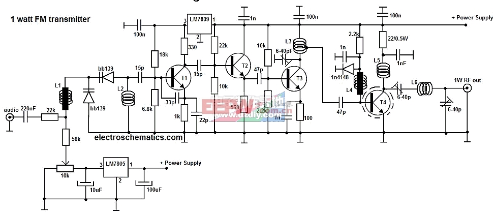
Components values:T1 = T2 = T3 = BF199T4 = 2N4427, BLX65, 2N3866, 2N3553L1 = rf choke (20 turns, 0.2mm on ferrite core, 0.3mm)L2 = 4 t, 0.7mm, 4mmL3 = 6 t, 0.8mm, 6mm, at first turn from T3L4 = 10 t, 0.2mm over ferrite coreL5 = 7 t, 0.8mm, 6mmL6 = 4 t, 1mm, 8mm, 10mm long
This 1 watt fm transmitter has been tested and is working as mentioned in this article. If you use replacement components the performances can vary a lot.


 Components values:T1 = T2 = T3 = BF199T4 = 2N4427, BLX65, 2N3866, 2N3553L1 = rf choke (20 turns, 0.2mm on ferrite core, 0.3mm)L2 = 4 t, 0.7mm, 4mmL3 = 6 t, 0.8mm, 6mm, at first turn from T3L4 = 10 t, 0.2mm over ferrite coreL5 = 7 t, 0.8mm, 6mmL6 = 4 t, 1mm, 8mm, 10mm longThis 1 watt fm transmitter has been tested and is working as mentioned in this article. If you use replacement components the performances can vary a lot.