Tuned-bandpass applicaTIons often incorporate switched-capacitor filters—these filters enable a sweep of the bandpass center frequency by simply sweeping the applied clock rate. Such an arrangement allows a processor-controlled system to detect mulTIple frequencies, for example.
But to achieve higher bandwidths with lower noise and distorTIon, many high-end applicaTIons employ continuous-time filter circuits composed of resistors, capacitors, op amps, and new filter ICs. Tuning these circuits is virtually impossible because their poles and Qs are set by fixed resistors.
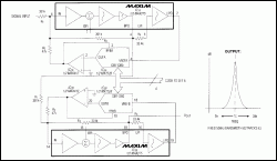
The addition of multiplying D/A converters provides a digital-tuning capability of continuous-time filters. In the 4th-order bandpass filter of Figure 1, for example, center frequency is proportional to the normalized digital code applied in parallel to the D/A converters: fC = √code(20kHz), where fC is the center frequency and code is normalized to 15/256...255/256 (the four LSBs are tied high to avoid excessive attenuation of the feedback signal). Because the converters change code simultaneously, they assure a smooth transition between center frequencies.
Code FFH, for instance, centers both 2nd-order filter sections at 20kHz with Qs of 25.8, resulting in a net (cascaded) Q of 40 and a bandwidth of 500kHz. Lower codes attenuate the feedback signal between lowpass output and the input of that section, reducing center frequency and Q in proportion across the range 5kHz to 20kHz. The passband remains a constant 500kHz.
In nontunable configurations, the bottom of R2 connects the lowpass (LPO) output, providing feedback that determines the filter's pole frequency and Q. In this circuit, a D/A converter attenuates each LPO signal before it gets to R2, providing software control of the frequency and Q. Because the output amplifier associated with each converter inverts the LPO signal, R2 must connect to IN (instead of BPI) to maintain the correct signal polarity.
Multiplying D/A converters can alter other feedback signals within the filter as well, providing digital control of Q alone (set by R3) and gain (set by R1), in addition to frequency. In other applications, the technique can produce adjustable-lowpass anti-aliasing filter that accommodates A/D converters with multiple sampling rates.

More detailed image
Figure 1. Three ICs—a dual filter, dual op amp, and a dual D/A converter—form an adjustable bandpass circuit that maintains a constant 500Hz bandpass over the center-frequency range 5kHz to 20kHz.


